- 您现在的位置:买卖IC网 > Sheet目录2003 > LTC1410IG#TR (Linear Technology)IC ADC 12BIT 1.25MSPS SMP 28SSOP
1
LTC1410
12-Bit, 1.25Msps Sampling
A/D Converter with Shutdown
S
FEATURE
D
U
ESCRIPTIO
The LTC
1410 is a 0.65
s, 1.25Msps, 12-bit sampling
A/D converter that draws only 160mW from
±5V supplies.
This easy-to-use device includes a high dynamic range
sample-and-hold, a precision reference and requires no
external components. Two digitally selectable power shut-
down modes provide flexibility for low power systems.
The LTC1410’s full-scale input range is
±2.5V. Maximum
DC specifications include
±1LSB INL and ±1LSB DNL over
temperature. Outstanding AC performance includes 71dB
S/(N + D) and 82dB THD at the Nyquist input frequency of
625kHz.
The unique differential input sample-and-hold can acquire
single-ended or differential input signals up to its 20MHz
bandwidth. The 60dB common mode rejection allows
users to eliminate ground loops and common mode noise
by measuring signals differentially from the source.
The ADC has a
P compatible, 12-bit parallel output port.
There is no pipeline delay in the conversion results. A
separate convert start input and a data ready signal (BUSY)
ease connections to FIFOs, DSPs and microprocessors.
s
1.25Msps Sample Rate
s
Power Dissipation: 160mW
s
71dB S/(N + D) and 82dB THD at Nyquist
s
No Pipeline Delay
s
Nap (7mW) and Sleep (10
W) Shutdown Modes
s
Operates with Internal 15ppm/
°C Reference
or External Reference
s
True Differential Inputs Reject Common Mode Noise
s
20MHz Full Power Bandwidth Sampling
s
±2.5V Bipolar Input Range
s
28-Pin SO Wide Package
U
S
A
O
PPLICATI
s
Telecommunications
s
Digital Signal Processing
s
Multiplexed Data Acquisition Systems
s
High Speed Data Acquisition
s
Spectrum Analysis
s
Imaging Systems
, LTC and LT are registered trademarks of Linear Technology Corporation.
U
A
O
PPLICATI
TYPICAL
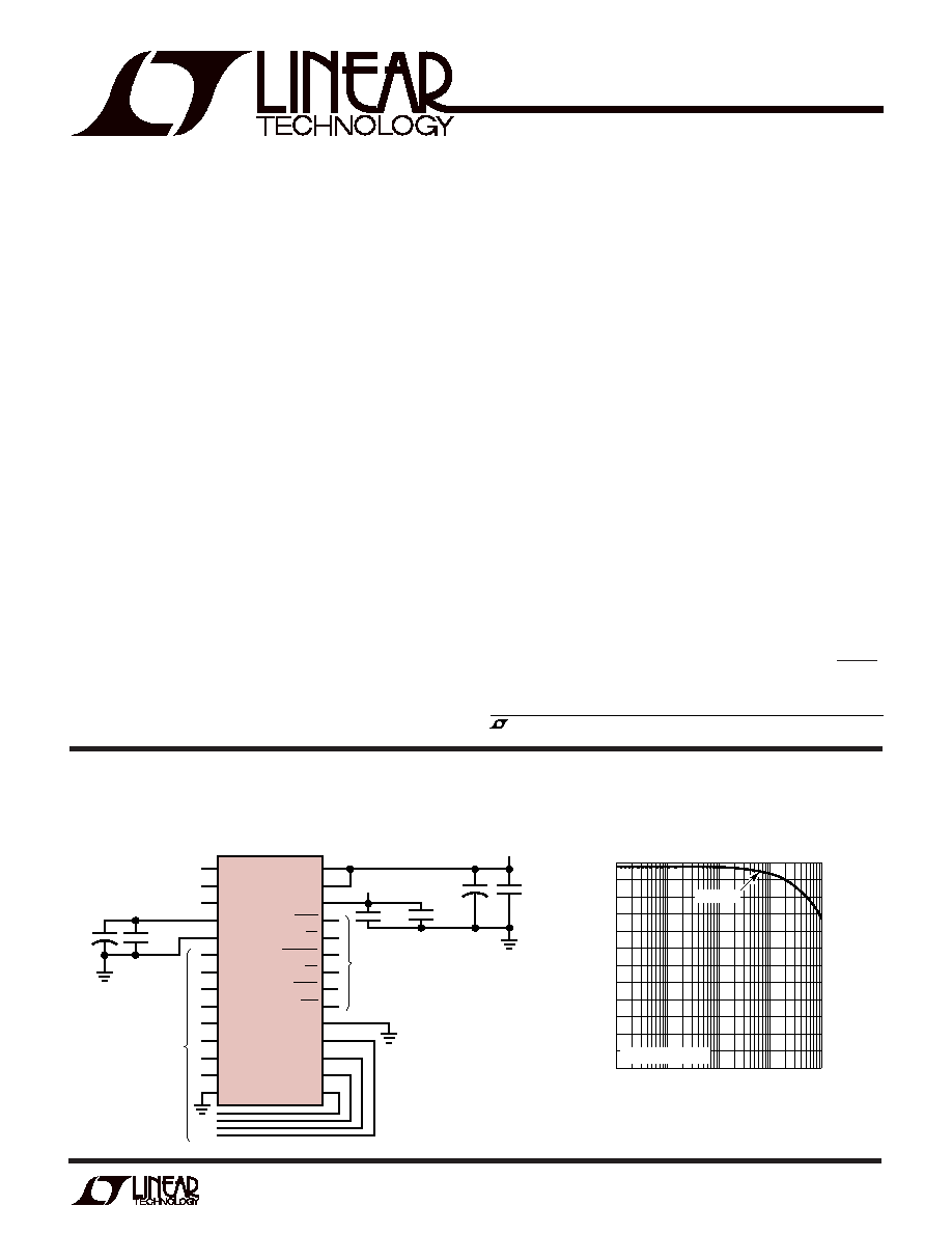
Complete 1.25MHz, 12-Bit Sampling A/D Converter
Effective Bits and Signal-to-(Noise + Distortion)
vs Input Frequency
INPUT FREQUENCY (Hz)
2
EFFECTIVE
BITS
S/(N
+
D)
(dB)
4
6
8
10
10k
100k
1M
10M
LTC1410 TA02
0
1k
12
74
68
62
56
50
fSAMPLE = 1.25MHz
NYQUIST
1
2
3
4
5
6
7
8
9
10
11
12
13
14
28
27
26
25
24
23
22
21
20
19
18
17
16
15
LTC1410
0.1
F
+
10
F
DIFFERENTIAL
ANALOG INPUT
(–2.5V TO 2.5V)
2.50V
VREF OUTPUT
10
F
10
F
0.1
F
0.1
F
–5V
5V
12-BIT
PARALLEL
BUS
P CONTROL
LINES
1410 TA01
+
+AIN
–AIN
VREF
REFCOMP
AGND
D11(MSB)
D10
D9
D8
D7
D6
D5
D4
DGND
AVDD
DVDD
VSS
BUSY
CS
CONVST
RD
SHDN
NAP/SLP
OGND
D0
D1
D2
D3
发布紧急采购,3分钟左右您将得到回复。
相关PDF资料
LTC1411IG#TRPBF
IC A/D CONV 14BIT 2.5MSPS 36SSOP
LTC1412IG#TR
IC ADC 12BIT 3MSPS SAMPLE 28SSOP
LTC1414IGN#TRPBF
IC A/D CONV 14BIT SAMPLNG 28SSOP
LTC1415CG#TRPBF
IC A/D CONV 12BIT SAMPLNG 28SSOP
LTC1416IG#TR
IC ADC 14BIT 400KSPS SMPL 28SSOP
LTC1417AIGN#TR
IC ADC 14BIT 400KSPS SMPL 16SSOP
LTC1418ACG#TRPBF
IC A/D CONV 14BIT SRL&PAR 28SSOP
LTC1419AISW#TRPBF
IC A/D CONV 14BIT SAMPLNG 28SOIC
相关代理商/技术参数
LTC1410IG#TRPBF
功能描述:IC A/D CONV 12BIT SAMPLNG 28SSOP RoHS:是 类别:集成电路 (IC) >> 数据采集 - 模数转换器 系列:- 标准包装:1,000 系列:- 位数:12 采样率(每秒):300k 数据接口:并联 转换器数目:1 功率耗散(最大):75mW 电压电源:单电源 工作温度:0°C ~ 70°C 安装类型:表面贴装 封装/外壳:24-SOIC(0.295",7.50mm 宽) 供应商设备封装:24-SOIC 包装:带卷 (TR) 输入数目和类型:1 个单端,单极;1 个单端,双极
LTC1410ISW
功能描述:IC A/D CONV 12BIT SAMPLNG 28SOIC RoHS:否 类别:集成电路 (IC) >> 数据采集 - 模数转换器 系列:- 标准包装:1,000 系列:- 位数:12 采样率(每秒):300k 数据接口:并联 转换器数目:1 功率耗散(最大):75mW 电压电源:单电源 工作温度:0°C ~ 70°C 安装类型:表面贴装 封装/外壳:24-SOIC(0.295",7.50mm 宽) 供应商设备封装:24-SOIC 包装:带卷 (TR) 输入数目和类型:1 个单端,单极;1 个单端,双极
LTC1410ISW#PBF
功能描述:IC A/D CONV 12BIT SAMPLNG 28SOIC RoHS:是 类别:集成电路 (IC) >> 数据采集 - 模数转换器 系列:- 标准包装:1,000 系列:- 位数:12 采样率(每秒):300k 数据接口:并联 转换器数目:1 功率耗散(最大):75mW 电压电源:单电源 工作温度:0°C ~ 70°C 安装类型:表面贴装 封装/外壳:24-SOIC(0.295",7.50mm 宽) 供应商设备封装:24-SOIC 包装:带卷 (TR) 输入数目和类型:1 个单端,单极;1 个单端,双极
LTC1410ISW#TR
功能描述:IC ADC 12BIT 1.25MSPS SMP 28SOIC RoHS:否 类别:集成电路 (IC) >> 数据采集 - 模数转换器 系列:- 标准包装:1,000 系列:- 位数:12 采样率(每秒):300k 数据接口:并联 转换器数目:1 功率耗散(最大):75mW 电压电源:单电源 工作温度:0°C ~ 70°C 安装类型:表面贴装 封装/外壳:24-SOIC(0.295",7.50mm 宽) 供应商设备封装:24-SOIC 包装:带卷 (TR) 输入数目和类型:1 个单端,单极;1 个单端,双极
LTC1410ISW#TRPBF
功能描述:IC A/D CONV 12BIT SAMPLNG 28SOIC RoHS:是 类别:集成电路 (IC) >> 数据采集 - 模数转换器 系列:- 标准包装:1,000 系列:- 位数:12 采样率(每秒):300k 数据接口:并联 转换器数目:1 功率耗散(最大):75mW 电压电源:单电源 工作温度:0°C ~ 70°C 安装类型:表面贴装 封装/外壳:24-SOIC(0.295",7.50mm 宽) 供应商设备封装:24-SOIC 包装:带卷 (TR) 输入数目和类型:1 个单端,单极;1 个单端,双极
LTC1411CG
功能描述:IC A/D CONV 14BIT 2.5MSPS 36SSOP RoHS:否 类别:集成电路 (IC) >> 数据采集 - 模数转换器 系列:- 标准包装:1 系列:- 位数:14 采样率(每秒):83k 数据接口:串行,并联 转换器数目:1 功率耗散(最大):95mW 电压电源:双 ± 工作温度:0°C ~ 70°C 安装类型:通孔 封装/外壳:28-DIP(0.600",15.24mm) 供应商设备封装:28-PDIP 包装:管件 输入数目和类型:1 个单端,双极
LTC1411CG#PBF
功能描述:IC ADC 14BIT 2.5MSPS 36SSOP RoHS:是 类别:集成电路 (IC) >> 数据采集 - 模数转换器 系列:- 标准包装:1 系列:- 位数:14 采样率(每秒):83k 数据接口:串行,并联 转换器数目:1 功率耗散(最大):95mW 电压电源:双 ± 工作温度:0°C ~ 70°C 安装类型:通孔 封装/外壳:28-DIP(0.600",15.24mm) 供应商设备封装:28-PDIP 包装:管件 输入数目和类型:1 个单端,双极
LTC1411CG#TR
功能描述:IC A/D CONV 14BIT 2.5MSPS 36SSOP RoHS:否 类别:集成电路 (IC) >> 数据采集 - 模数转换器 系列:- 标准包装:1 系列:- 位数:14 采样率(每秒):83k 数据接口:串行,并联 转换器数目:1 功率耗散(最大):95mW 电压电源:双 ± 工作温度:0°C ~ 70°C 安装类型:通孔 封装/外壳:28-DIP(0.600",15.24mm) 供应商设备封装:28-PDIP 包装:管件 输入数目和类型:1 个单端,双极